


CyroHEMT提供基于HEMT技术的极低噪声低温放大器,其可在20 mK的极低温下稳定工作,而且在特定频率可达到 aA/Hz½ 的极低噪声电流和亚nV/Hz1/2 的极低噪声电压,可应用在低温探测器读出、扫描隧道显微镜、量子计算等前沿科学研究中。
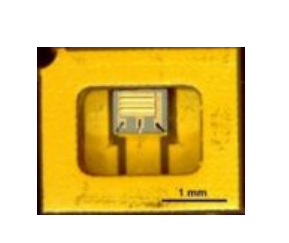
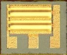
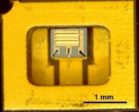
CryoHEMTs: chip or packaged in ceramic SOT23
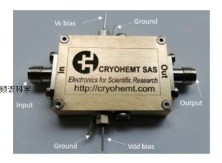
CryoHEMTs based cryogenic preamplifiers
CryoHEMTs: chip or packaged in ceramic SOT23
Characteristics of available cryoHEMTs with various gate-surface measured at 4.2 K, Ids = 1 mA and Vds = 100 mV:
| Denomination | 200pch | 100pch | 30pch | 5pch | 1pch | |
| LgxW (µm²) | 1.5×10⁵ | 6.4×10⁴ | 2.0×10⁴ | 2.0×10³ | 4.0×10² | |
| Cgs (pF); Cgd (pF) | 236; 8.9 | 103; 8.9 | 33; 3.5 | 4.6; 1.0 | 1.8; ~0.6 | |
| Vds(mV); Ids(mA) | 100; 1.0 | 100; 1.0 | 100; 1.0 | 100; 1.0 | 100; 0.5 | |
| gm (mS); gd (mS) | 52; 0.4 | 40; 1.2 | 115; 1.3 | 44; 1.3 | 15; 0.8 | |
| ft = gm/(2πCgs) (Hz) | 3.5×10⁷ | 6.2×10⁷ | 5.5×10⁸ | 1.5×10⁹ | 1.3×10⁹ | |
| en (nV/Hz½) | @1Hz @10Hz @100Hz @1kHz | ~ 5.4 ~ 1.8 ~ 0.55 ~ 0.25 | 11 – 14 4 – 5 ~ 1 ~ 0.4 | ~ 15 ~ 5.5 1.5 – 2 0.6 – 0.7 | 35 – 50 10 – 15 2.5 – 5 0.75 – 1.2 | 80 – 100 30 – 40 8 – 10 2 – 4 |
| en-white (nV/Hz½) | ~ 0.18 | ~ 0.21 | 0.15 – 0.18 | ~ 0.24 | 0.4 – 0.5 | |
| in (aA/Hz½) | @1Hz @1kHz | 21 6.8×10² | 15 5.1×10² | 9.1 2.4×10² | 2.2 70 | 3.6 57 |
LgxW is the gate surface; Cgs, the gate-source capacitance; Cgd, the gate-drain capacitance; Vds, the drain-source bias; Ids, the drain-source current; gm, the transconductance; gd, the output conductance; ft, the current-gain cutoff frequency; en, the equivalent input noise voltage; en-white, the equivalent input white noise voltage; in, the equivalent input noise current. Noise current is measured with the help of the capacitance input setup shown in the reference Appl. Phys. Lett. 105, 13504 (2014).
CryoHEMTs based cryogenic preamplifiers
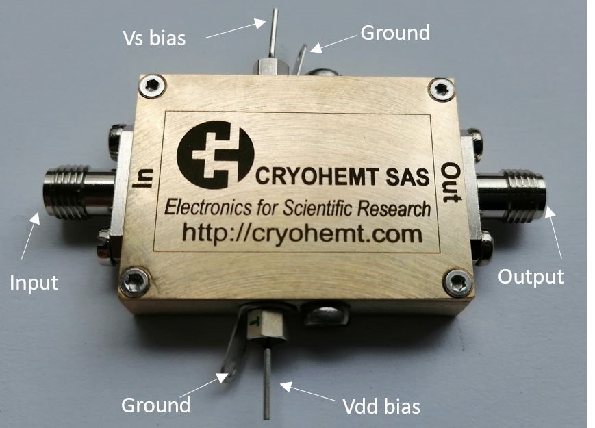
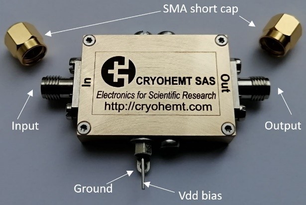
Various cryogenic readout electronics have been realized with cryoHEMTs and performed (see papers in “PUBLICATIONS”), a few examples are as below. We can propose and provide several types of cryo-amp to meet specific experimental requirement, e.g., set the output impedance of 50Ω for operating frequency » 1 MHz; minimize the Miller effect and the input capacitance by adding a follower (common-drain amp). All our cryo-amps can be modified and optimized to fit user’s needs.
Datasheet of following plug-and-play cryo-amps are biased with two votage sources. The cryo-amps can also be biased with only one voltage source, but the datasheet can be changed, e.g., the low-frequency limit and the power dissipation. The box dimension (without SMA and feedthrough) of the cryo-amps is 36mmX26mmX8mm.
The cryo-amp A5-1 is based on a 5pch with the DC coupling input: datasheet and some of resulted publications:
| Model: A5-1 | 5pch cryoHEMT |
| Operating temperature | ≤ 4.2 K |
| Input coupling | DC |
| Input impedance | 11 pF // 1016 Ω |
| Output coupling | DC |
| Output impedance | 132 Ω |
| *Bandwidth, including the input impedance of 50 Ω, the power lines’ resistance of 1 Ω and the output cable’s capacitance of 200 pF | 0 Hz – 6 MHz |
| **Voltage gain Avo | ~ 5 |
| ***Vout_p-t-p = 90 mV | Av/Avo = 95% |
| Power dissipation | ~ 0.35 mW |
| HEMT’s Noise voltages @ 4.2 K | 9.8 ~ 12 nV/Hz½ at 10 Hz 0.66 ~ 0.93 nV/Hz½ at 1 kHz 0.25 nV/Hz½ at 100 kHz 0.24 nV/Hz½ at 1 MHz |
| **** HEMT’s Noise currents @ 4.2 K | 6 aA/Hz½ at 10 Hz 62 aA/Hz½ at 1 kHz 0.7 fA/Hz½ at 100 kHz 2 fA/Hz½ at 1 MHz |
* The high frequency limit partially depends on amp’s output impedance and the capacitance of the cable that connects the cryo-amp to the room temperature electronics. By setting 50 Ω output, the cutoff frequency can be about 420 MHz. ** Avo is the small signal voltage gain. Avo can be increased (or decreased) by increasing (or decreasing) the output impedance, the change of the output impedance induces the change of the power dissipation and the high-frequency limit of the cryo-amp. *** The voltage gain Av depends on its output peak-to-peak amplitude Vout_p-t-p, Av decreases with the increase of Vout_p-t-p due to the limit of the working point.**** The noise current is measured in a HEMT with the same configuration by the capacitor input method, see Applied Physics Letters 105, 1, 013504 (2014)
Quantum limit of heat flow across a single electronic channel
Science 342, 601 (2013)Hong-Ou-Mandel experiment for temporal investigation of single electron fractionalization
Nature Communications 6, 6854 (2015)Primary thermometry triad at 6 mK in mesoscopic circuits
Nature Communications 7, 12908 (2016)Heat Coulomb blockade of one ballistic channel
Nature Physics 14(2), 145-148 (2018)Charge trapping and super-Poissonian noise centres in a cuprate superconductor
Nature Physics, 14, 1183 (2018)Noisy defects in the high-Tc superconductor Bi2Sr2CaCu2O8+x
Nature Communications 10, 544 (2019)Atomic scale shot-noise using cryogenic MHz circuitry
Review of Scientific Instruments 89, 093708 (2018)Amplifier for scanning tunneling microscopy at MHz frequencies
Review of Scientific Instruments 89, 093709 (2018)Atomic manipulation of the gap in Bi2Sr2CaCu2O8+x
Science 367, 6473, 68 (Supplementary Materials) (2020)Improving the read-out of the resonance frequency of nanotube mechanical resonators
Applied Physics Letters 113, 063104 (2018)Ultrasensitive displacement noise measurement of carbon nanotube mechanical resonators
Nano Letters 18, 5324 (2018)Cooling and self-oscillation in a nanotube electromechanical resonator
Nature Physics 16, 32 (2020)Fractional statistics in anyon collisions
Science 368, 6487, 173-177 (2020)
The cryo-amp A5ac-1 is based on a 5pch with the AC coupling input: datasheet
| Amp model: A5ac-1 | 5pch cryoHEMT |
| Operating temperature | ≤ 4.2 K |
| Input coupling | AC |
| Input impedance | 11 pF // 1.3 GΩ |
| Output coupling | DC |
| Output impedance | 132 Ω |
| *Bandwidth, including the input impedance of 50 Ω, the power lines’ resistance of 1 Ω and the output cable’s capacitance of 200 pF | 12 mHz – 6 MHz |
| **Voltage gain Avo | ~ 5 |
| ***Vout_p-t-p = 90 mV | Av/Avo = 95% |
| Power dissipation | ~ 0.35 mW |
| HEMT’s Noise voltages @ 4.2 K | 9.8 ~ 12 nV/Hz½ at 10 Hz 0.66 ~ 0.93 nV/Hz½ at 1 kHz 0.25 nV/Hz½ at 100 kHz 0.24 nV/Hz½ at 1 MHz |
| **** HEMT’s Noise currents @ 4.2 K | 6 aA/Hz½ at 10 Hz 62 aA/Hz½ at 1 kHz 0.7 fA/Hz½ at 100 kHz 2 fA/Hz½ at 1 MHz |
* The high frequency limit partially depends on amp’s output impedance and the capacitance of the cable that connects the cryo-amp to the room temperature electronics. By setting 50 Ω output, the cutoff frequency can be about 420 MHz. ** Avo is the small signal voltage gain. Avo can be increased (or decreased) by increasing (or decreasing) the output impedance, the change of the output impedance induces the change of the power dissipation and the high-frequency limit of the cryo-amp. *** The voltage gain Av depends on its output peak-to-peak amplitude Vout_p-t-p, Av decreases with the increase of Vout_p-t-p due to the limit of the working point.**** The noise current is measured in a HEMT with the same configuration by the capacitor input method, see Applied Physics Letters 105, 1, 013504 (2014)
The cryo-amp A200-1 is based on a 200pch with the DC coupling input: datasheet
| Amp model: A200-1 | 200pch cryoHEMT |
| Operating temperature | ≤ 4.2 K |
| Input coupling | DC |
| Input impedance | 266 pF // 1016 Ω |
| Output coupling | DC |
| Output impedance | 106 Ω |
| *Bandwidth, including the input impedance of 50 Ω, the power lines’ resistance of 1 Ω and the output cable’s capacitance of 200 pF | 0 Hz – 5.7 MHz |
| **Voltage gain Avo | ~ 5 |
| ***Vout_p-t-p = 90 mV | Av/Avo = 95% |
| Power dissipation | ~ 0.3 mW |
| HEMT’s Noise voltages @ 4.2 K | 2 nV/Hz½ at 10 Hz 0.54 nV/Hz½ at 100 Hz 0.24 nV/Hz½ at 1 kHz 0.19 nV/Hz½ at 10 kHz 0.18 nV/Hz½ at 100 kHz |
| **** HEMT’s Noise currents @ 4.2 K | 70 aA/Hz½ at 10 Hz 0.21 fA/Hz½ at 100 Hz 0.68 fA/Hz½ at 1 kHz 2.1 fA/Hz½ at 10 kHz 6.0 fA/Hz½ at 100 kHz |
* The high frequency limit partially depends on amp’s output impedance and the capacitance of the cable that connects the cryo-amp to the room temperature electronics. By setting 50 Ω output, the cutoff frequency can be about 420 MHz. ** Avo is the small signal voltage gain. Avo can be increased (or decreased) by increasing (or decreasing) the output impedance, the change of the output impedance induces the change of the power dissipation and the high-frequency limit of the cryo-amp. *** The voltage gain Av depends on its output peak-to-peak amplitude Vout_p-t-p, Av decreases with the increase of Vout_p-t-p due to the limit of the working point.**** The noise current is measured in a HEMT with the same configuration by the capacitor input method, see Applied Physics Letters 105, 1, 013504 (2014)
The cryo-amp A200ac-1 is based on a 200pch with the AC coupling input: datasheet
| Amp model: A200ac-1 | 200pch cryoHEMT |
| Operating temperature | ≤ 4.2 K |
| Input coupling | AC |
| Input impedance | 266 pF // 1.3 GΩ |
| Output coupling | DC |
| Output impedance | 106 Ω |
| *Bandwidth, including the input impedance of 50 Ω, the power lines’ resistance of 1 Ω and the output cable’s capacitance of 200 pF | 12 mHz – 5.7 MHz |
| **Voltage gain Avo | ~ 5 |
| ***Vout_p-t-p = 90 mV | Av/Avo = 95% |
| Power dissipation | ~ 0.3 mW |
| HEMT’s Noise voltages @ 4.2 K | 2 nV/Hz½ at 10 Hz 0.54 nV/Hz½ at 100 Hz 0.24 nV/Hz½ at 1 kHz 0.19 nV/Hz½ at 10 kHz 0.18 nV/Hz½ at 100 kHz |
| **** HEMT’s Noise currents @ 4.2 K | 70 aA/Hz½ at 10 Hz 0.21 fA/Hz½ at 100 Hz 0.68 fA/Hz½ at 1 kHz 2.1 fA/Hz½ at 10 kHz 6.0 fA/Hz½ at 100 kHz |
* The high frequency limit partially depends on amp’s output impedance and the capacitance of the cable that connects the cryo-amp to the room temperature electronics. By setting 50 Ω output, the cutoff frequency can be about 420 MHz. ** Avo is the small signal voltage gain. Avo can be increased (or decreased) by increasing (or decreasing) the output impedance, the change of the output impedance induces the change of the power dissipation and the high-frequency limit of the cryo-amp. *** The voltage gain Av depends on its output peak-to-peak amplitude Vout_p-t-p, Av decreases with the increase of Vout_p-t-p due to the limit of the working point.**** The noise current is measured in a HEMT with the same configuration by the capacitor input method, see Applied Physics Letters 105, 1, 013504 (2014)

